- 您现在的位置:买卖IC网 > Sheet目录1991 > CS4382A-DQZ (Cirrus Logic Inc)IC DAC 8CH 114DB 192KHZ 48-LQFP
DS618F2
11
CS4382A
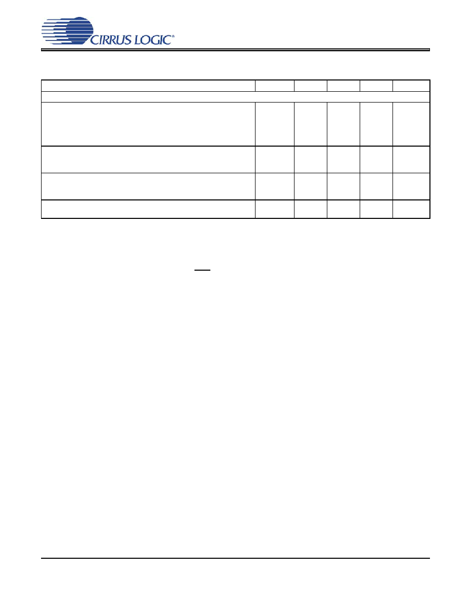
POWER AND THERMAL CHARACTERISTICS
Notes:
4.
Current consumption increases with increasing FS within a given speed mode and is signal-dependent.
Max values are based on highest FS and highest MCLK.
5.
ILC measured with no external loading on the SDA pin.
6.
Power-down Mode is defined as RST pin = Low with all clock and data lines held static.
7.
Parameters
Symbol
Min
Typ
Max
Units
Power Supplies
Power Supply Current
Normal Operation, VA= 5 V
VD= 2.5 V
(Note 5) Interface Current, VLC=5 V
VLS=5 V
(Note 6) Power-down State (all supplies)
IA
ID
ILC
ILS
Ipd
-
84
20
2
75
200
91
25
-
mA
A
Power Dissipation (Note 4)
VA = 5V, VD = 2.5V
Normal Operation
(Note 6) Power-down
-
470
1
520
-
mW
Package Thermal Resistance
Multi-layer
Two-layer
θJA
θJC
-
48
65
15
-
°C/Watt
Power Supply Rejection Ratio (Note 7)
(1 kHz)
(60 Hz)
PSRR
-
60
40
-
dB
发布紧急采购,3分钟左右您将得到回复。
相关PDF资料
CS4384-CQZR
IC DAC 8CH 103DB 192KHZ 48-LQFP
CS4385-DQZR
IC DAC 8CH 114DB 192KHZ 48-LQFP
CS4391A-KZZR
IC DAC 24BIT 192KHZ W/VC 20TSSOP
CS4392-KZZ
IC DAC 24BIT 192KHZ W/VC 20TSSOP
CS4397-KSZ
IC DAC 24BIT MULTY STNDRD 28SOIC
CS4398-CZZ
IC DAC 120DB 192KHZ W/VC 28TSSOP
CS43L22-CNZR
IC DAC W/HDPN & SPKR AMPS 40-QFN
CS4461-CZZR
IC ADC PSR FEEDBACK 24-TSSOP
相关代理商/技术参数
CS4382A-DQZR
功能描述:音频数/模转换器 IC IC 114dB 192 kHz 8Chn DAC w/DSD supt. RoHS:否 制造商:Texas Instruments 转换器数量: 分辨率:16 bit 接口类型:I2S, UBS 转换速率: 信噪比:98 dB 工作电源电压:5 V DAC 输出端数量:2 工作温度范围:- 25 C to + 85 C 电源电流:23 mA 安装风格:SMD/SMT 封装 / 箱体:TQFP-32 封装:Reel
CS4382A-EQZ
制造商:CIRRUS 制造商全称:Cirrus Logic 功能描述:114 dB, 192 kHz 8-channel D/A Converter
CS4382A-EQZR
制造商:CIRRUS 制造商全称:Cirrus Logic 功能描述:114 dB, 192 kHz 8-channel D/A Converter
CS4382-KQZ
功能描述:数模转换器- DAC IC 114dB 24-bit 102kHz 8Ch DAC RoHS:否 制造商:Texas Instruments 转换器数量:1 DAC 输出端数量:1 转换速率:2 MSPs 分辨率:16 bit 接口类型:QSPI, SPI, Serial (3-Wire, Microwire) 稳定时间:1 us 最大工作温度:+ 85 C 安装风格:SMD/SMT 封装 / 箱体:SOIC-14 封装:Tube
CS4382-KQZR
功能描述:数模转换器- DAC IC 114dB 24-bit 102kHz 8Ch DAC RoHS:否 制造商:Texas Instruments 转换器数量:1 DAC 输出端数量:1 转换速率:2 MSPs 分辨率:16 bit 接口类型:QSPI, SPI, Serial (3-Wire, Microwire) 稳定时间:1 us 最大工作温度:+ 85 C 安装风格:SMD/SMT 封装 / 箱体:SOIC-14 封装:Tube
CS4383
制造商:CIRRUS 制造商全称:Cirrus Logic 功能描述:114 dB, 192 kHz 8-Channel D/A Converter
CS4383-BQ
制造商:CIRRUS 制造商全称:Cirrus Logic 功能描述:114 dB, 192 kHz 8-Channel D/A Converter
CS4383-KQ
制造商:CIRRUS 制造商全称:Cirrus Logic 功能描述:114 dB, 192 kHz 8-Channel D/A Converter